Manufacturability Testing (Design For Manufacturing)
Blog Post 1.02.02 - Prototype Your Parts Before They Leave Engineering
What is Manufacturability Testing and how can it reduce and eliminate shop floor rework? Read More ...
Global Edge Video Blog-1.02

Prototype Your Parts Before They Leave Engineering
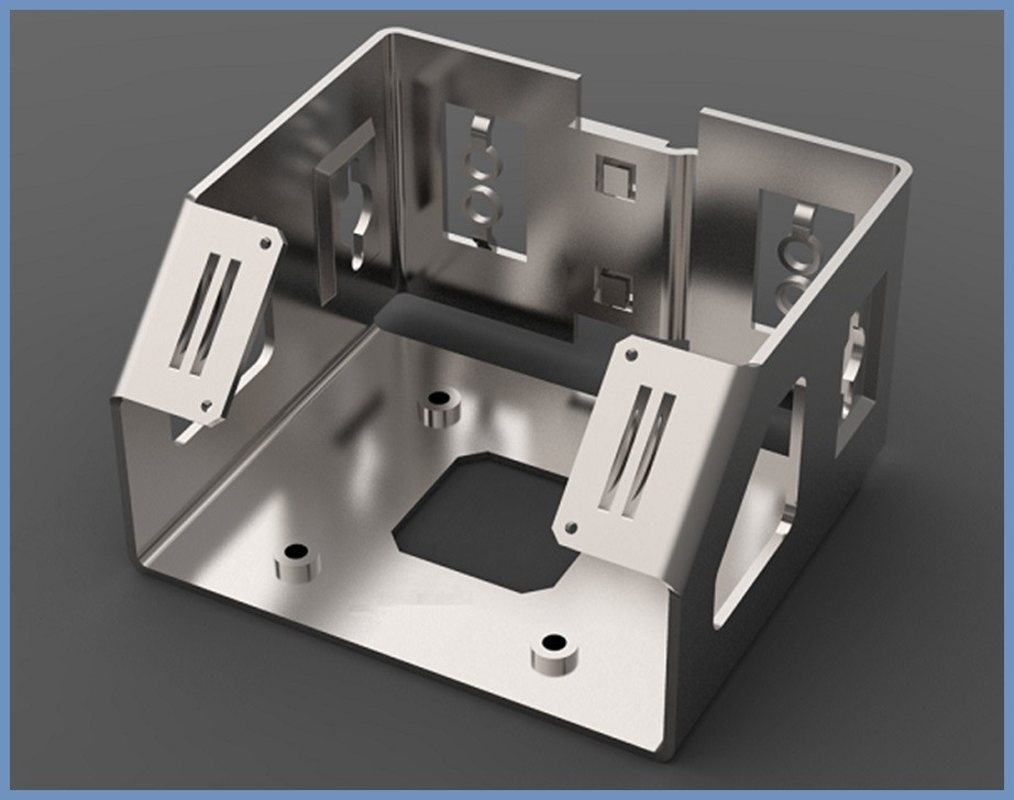
An expensive component of the prototyping process is the trial-and-error time of fabricating a sheet metal part. This is especially true for contract manufacturers when their customers provide them with a wide multitude of sheet metal parts that need to be first prototyped before they are put in wider production. Many considerations come into play with the following considerations:
Material
- Proper Material Type
- Proper Material Thickness
- Proper Material Finish
Bending Machine Tool Capabilities
- Within Tooling Limits
- Bend Angles Within Allowable Limits
- Part Within Bend Tonnage Limit
- Part Flange Size Within Allowable Limits
- Internal Bend Heights
Hole / Embossment / Louver / Special Features Locations
- Placement of Pem Holes from Bend Lines
- Embossment / Louver Placement
- Special Feature Interferes with Flange
Hardware Specifications
- Proper Matching of Hardware
Global Edge Engineering Assistant provides a simplified method to identify potential common sheet metal fabrication errors taking into consideration items from the above list. Simplifying the prototyping process starts with the automated analysis of CAD sheet metal parts which includes the importation and database capture of the following CAD Part Parameters:
- Material / Thickness / Part Weight / Bend Radius
- Blank / Flat (Length & Width)
- Cutouts / Holes (Count & Size)
- Minimum / Maximum Bend Length
- Minimum / Maximum Bend Angle
- Minimum / Maximum Flange Width
- Minimum Pem Hole to Bend Line Gap
- Minimum Embossment to Bend Line Gap
- Minimum Louver to Bend Line Gap
- Maximum Up / Maximum Down Bend
- Fold / Hem / Extrude Counts
- Minimum Taper / Die Cut to Bend Line Gap
These CAD part parameters are subsequently stored in the Global Edge database to serve as a foundation for a “Manufacturability Testing” process. The CAD part parameters include identification up and down bends counts, location of Pem Hole and Louver distance from a bend line, including cutout counts and cutout perimeters, etc.
Sample CAD Part Parameters
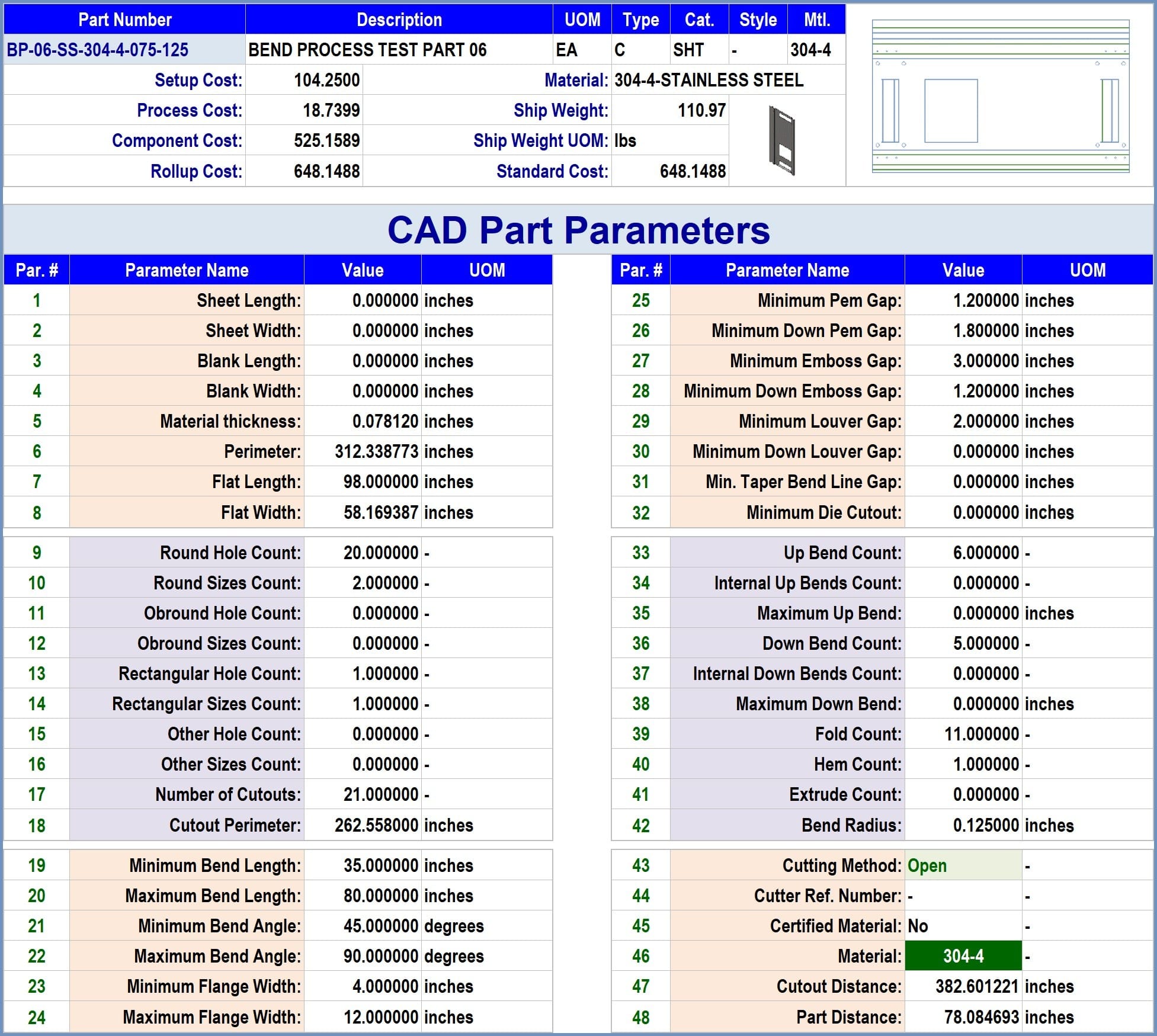
As part of the CAD part analysis, Global Edge Engineering Assistant automatically identifies and matches the sheet metal part with the proper user definable Bend Processes as illustrated with the following Sample Bend Process:
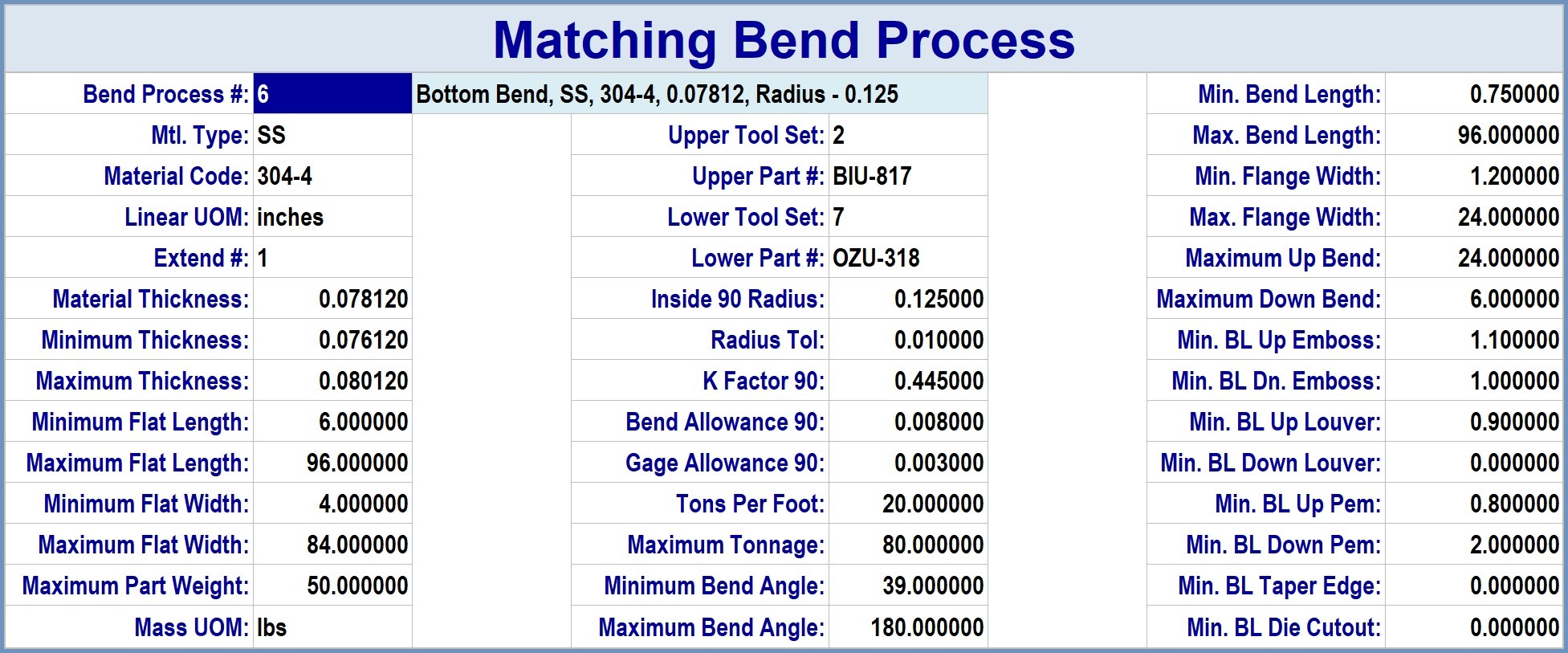
As Global Edge Engineering Assistant completes the importation and storage of the CAD part parameters, the software automatically generates routings based on those parameters:
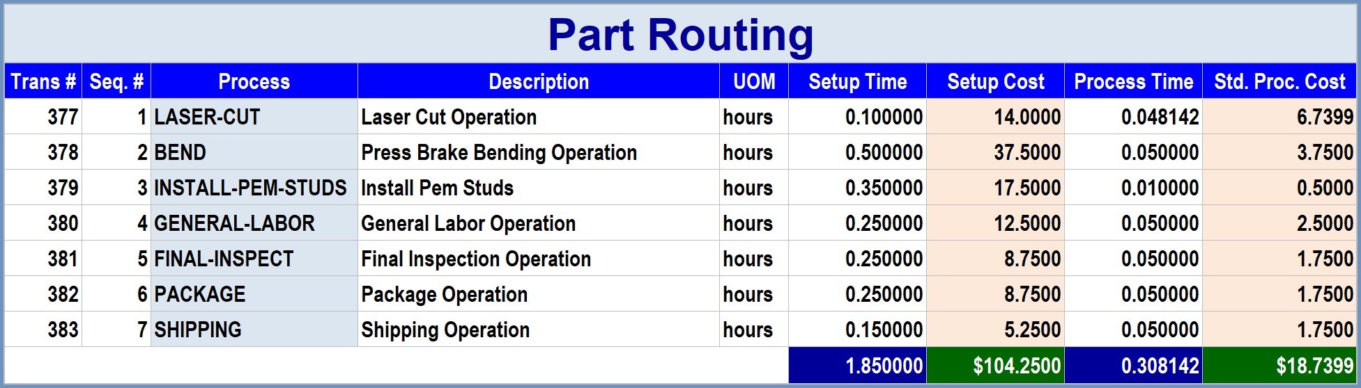
During the generation of the routings, Global Edge Engineering Assistant automatically determines if the sheet metal part can be successfully fabricated with each of the routing steps. For example, with the “Press Brake Bending Operation”, the software automatically determines whether the sheet metal part can be successfully bent comparing the CAD Part Parameters with the matching Bend Process. This includes the automatic execution of a “Manufacturability Test” that allows the engineer to view the test results:
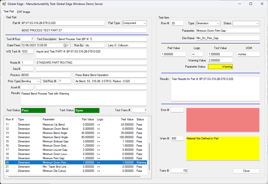
The above and below example includes 22 tests that were performed on the selected part. The highlighted test below (Minimum Down Pem Gap) detected a warning that “Feature Within Warning Gap”. The matching Bend Process for the sheet metal part requires the Minimum Down Pem Gap is at least 1.500000 inches from the nearest bend line. The detected gap with the selected sheet metal part is 1.800000 inches, which indicates the gap is allowable. However, a Warning Message is detected because ideally with the matching Bend Process indicates that the Minimum Down Pem Gap should ideally be at least 2.000000 inches.
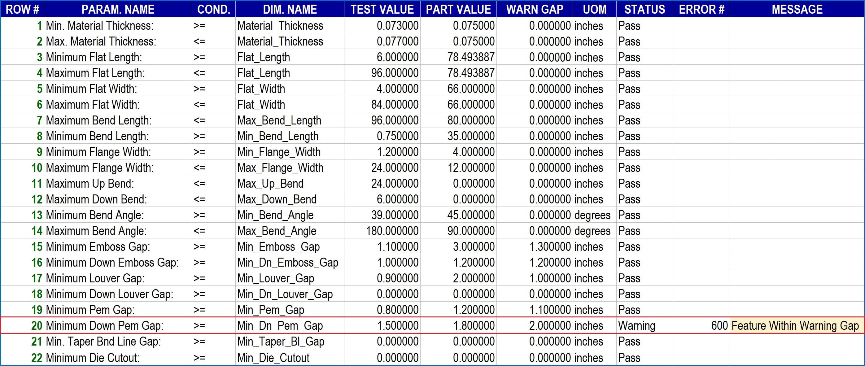
When a manufacturability test fails one or more tests, the engineer can make the appropriate change(s) to the necessary 3D CAD Sheet Metal Model and repeat the Manufacturability Test until the errors are corrected. The Global Edge Engineering Assistant provides an innovative software tool that helps speed up the whole prototyping process and eliminates shop floor rework by getting things right the first time before a part reaches the shop floor.
Summary
Global Edge Engineering Assistant can save your manufacturing operation significant time and money by reducing and significantly speed up the prototyping process. Global Edge Engineering Assistant helps get it right the first time with the following features and benefits:
- Significantly Reduces Prototyping Trial & Error Process
- Reduces Prototyping Costs
- Provides Engineering Design For Manufacturing Capabilities
Prototyping Parts Before They Leave Engineering
A Comprehensive Guide to Successful Sheet Metal Fabrication
In the world of manufacturing, the journey from engineering design to actual fabrication is fraught with challenges—and nowhere is this more apparent than in the prototyping of custom sheet metal parts. Before your part designs leave the engineering department, it’s essential to ensure they can be successfully fabricated, saving valuable time and resources while minimizing costly trial-and-error iterations. This is especially critical for contract manufacturers who work with a wide range of customer designs and must quickly prototype numerous components before moving to full-scale production.
This guide explores the key considerations at every stage of the prototyping process, offering practical insights to help engineers and manufacturers avoid common pitfalls and achieve the highest success rate in part fabrication.
The Importance of Early Prototyping
Prototyping bridges the gap between conceptual design and production. It is the phase where designs are validated for manufacturability, functionality, and compliance with all requirements. Investing effort in prototyping before parts leave engineering reduces production delays, prevents material wastage, and ensures that costly manufacturing resources are used efficiently. By thoroughly vetting designs, manufacturers can anticipate issues and optimize the process for scalability.
Key Considerations for Successful Sheet Metal Prototyping
Sheet metal fabrication demands precision and foresight. The following categories summarize the most critical factors to address before part designs transition out of engineering.
Material Selection
- Proper Material Type: The choice of material determines the physical properties of the part, its durability, corrosion resistance, and suitability for the intended application. Common sheet metals include aluminum, stainless steel, mild steel, and copper. It’s crucial to match the material to functional requirements—considering factors such as conductivity, weight, and exposure to harsh environments.
- Proper Material Thickness: Thickness impacts structural integrity, manufacturability, and compatibility with hardware. Thicker materials provide greater strength but may exceed equipment capacity or complicate bending operations. Conversely, very thin materials can result in parts that are too fragile or unsuitable for intended loads. Standard thicknesses should be referenced to ensure both design intent and manufacturability align.
- Proper Material Finish: Surface finish affects aesthetics, corrosion protection, and subsequent processing steps (like painting or powder coating). Specify finishes that are compatible with the fabrication process and final use—be it brushed, anodized, plated, or raw. Ensure clear communication of finish standards on engineering drawings to prevent rework and ambiguity.
Bending Machine Tool Capabilities
- Within Tooling Limits: Each bending machine has distinct tooling limitations. Parts must be designed so that bends do not exceed the maximum allowable depth, width, or radius the tooling can handle. Reviewing machine specifications beforehand prevents designs that cannot be physically accomplished.
- Bend Angles Within Allowable Limits: Extreme bend angles may cause cracking, stretching, or distortion of the material. Maintain bend angles within recommended limits for each material type and thickness, in line with manufacturer guidelines and industry best practices. Use bend allowance charts to calculate the precise dimensions after bending.
- Part Within Bend Tonnage Limit: The tonnage limit refers to the maximum force the press brake can exert. Exceeding this limit can damage both the equipment and the part. Calculate required tonnage based on material, thickness, and length to ensure parts are feasible for available equipment.
- Part Flange Size Within Allowable Limits: Flanges that are too small may not be supported adequately during bending, leading to deformation or inaccuracies. Design flanges with dimensions that are compatible with tooling fingers and support mechanisms. Consult with fabrication experts if uncertain.
- Internal Bend Heights: Internal bends should be tall enough to avoid interference with tooling and to maintain structural integrity. Short internal bends may compromise part strength or make assembly difficult.
Hole, Embossment, Louver, and Special Feature Placement
- Placement of Pem Holes from Bend Lines: Pem, or press-fit, holes are used for hardware insertion. Their placement relative to bend lines is crucial; holes too close to bends may distort during forming or interfere with hardware installation. Maintain minimum clearance distances as specified by hardware manufacturers to ensure reliable fitment.
- Embossment / Louver Placement: Embossments and louvers can enhance part rigidity or provide ventilation, but their placement must be coordinated with bend lines, cutouts, and flanges. Avoid locating features where they will be deformed by subsequent processes, and ensure adequate flat area for stamping operations.
- Special Feature Interferes with Flange: Features such as cutouts or tabs must not conflict with flanges, which could compromise assembly or strength. Use clear section views in drawings to highlight potential conflicts and resolve them before prototyping.
Hardware Specifications
- Proper Matching of Hardware: Fasteners, inserts, and other hardware must be compatible with both the material and the part geometry. Verify that the hardware selected matches specified hole sizes, thickness ranges, and finish requirements. Consult hardware suppliers for recommended installation practices and tolerances.
Practical Prototyping Strategies
Beyond design checks, effective prototyping employs several best practices to minimize errors and maximize yield:
- Review Engineering Drawings: Thoroughly check all dimensions, tolerances, and notes. Involve fabrication experts in the review process to identify any potential issues not apparent in CAD models alone.
- Simulate Manufacturing Processes: Use digital tools to simulate bending, punching, and forming operations. This can reveal potential collisions, material stresses, and process constraints before actual fabrication begins.
- Create Physical Mockups or 3D Printed Prototypes: When feasible, create mockups using less expensive materials or additive manufacturing techniques. These models can verify fit, assembly, and function, reducing risk before committing to costly sheet metal fabrication.
- Communicate with Contract Manufacturers: Share all relevant specifications, drawings, and feature requirements with your manufacturing partners. Open communication enables them to flag concerns early and suggest improvements for fabrication efficiency.
- Iterate and Document Changes: Expect iterative development. Document all changes made during prototyping and communicate updates to all stakeholders. This ensures lessons learned are captured for future projects and avoids confusion in production.
Common Prototyping Pitfalls and How to Avoid Them
- Overlooking Tolerances: Tight tolerances may be difficult or impossible to achieve depending on equipment and material. Clearly specify critical tolerances and allow for reasonable variation elsewhere.
- Insufficient Communication: Ambiguous or incomplete documentation can lead to incorrect fabrication. Always provide clear, detailed drawings and notes.
- Neglecting Post-Fabrication Processes: Consider how finishing, hardware installation, and assembly will affect the part. Design with the full process in mind to prevent issues downstream.
- Ignoring Equipment Limitations: Be aware of the capabilities and constraints of available machinery. Consult with fabrication teams to understand what is possible and adjust designs accordingly.
Conclusion
Prototyping is a critical phase in the transition from engineering to manufacturing. By rigorously evaluating every aspect of material choice, bending capabilities, feature placement, and hardware specifications, engineers can ensure that their part designs are not only innovative but also manufacturable. A successful prototyping process reduces costly errors, accelerates production timelines, and delivers reliable components that perform as intended.
Whether you’re a contract manufacturer handling a diverse array of sheet metal designs or an engineer developing a new part, following these guidelines helps ensure your prototypes are ready to succeed—before they ever leave engineering. By embracing a collaborative, detail-oriented approach, you lay the foundation for efficient fabrication and quality production, providing lasting value to your organization and customers alike.